
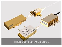


Brandnew fiber-coupled diode lasers, including 105um, 135um, 200um and other different fiber core diameter output, the laser power ranges from tens of watts to thousands of watts, and the output wavelength covers 400nm to 1000nm, with multiple single-tube coupling, high reliability, Anti-reflection protection, high photoelectric conversion rate, wide wavelength coverage and other characteristics, are widely used in industrial processing, precision processing, medical beauty, scientific research, sensing detection, lighting and other fields.
1. Safety precautions
Under normal circumstances, very little light is scattered from a bent fiber (due to bend losses), and it is relatively safe. But as long as the laser module is powered on, eye protection must still be done to prevent sudden strong light leakage caused by fiber damage/melting. Please strictly abide by the fourth-level infrared laser safety standards and take protective measures for eyes and skin.

2. Install the diode laser
a. As shown in Figure 2, place the laser module on a standard marble platform and check the flatness of the bottom of the shell to ensure that the shell itself is not deformed and the bottom plate has no pits.

b. Clean the heat sink surface with alcohol.
c. Referring to Figure 3, turn over the laser module and carefully clean the bottom of the housing with alcohol.

d. Evenly coat a layer of thermal conductive silicone grease on the bottom of the laser module, with a thickness of about 100um (as shown in Figure 4); then align the mounting holes and place the laser module on the cooling plate.


It is recommended to use a torque screwdriver to install the laser module. First set the torque to 0.15 N∙m, then turn the screw clockwise for 2-3 turns to slightly fix the screw; then set the torque of the torque wrench to 0.25N∙m, and then tighten the screw clockwise Several turns until the screw can no longer be tightened.

e. Confirm that the heat-conducting material overflows around the bottom of the laser module, as shown in Figure 7.

3. Circuit Connection
a. Static Protection
Electrostatic discharge is one of the important reasons leading to unexpected failure of semiconductor lasers. The installation of the laser must be completed by trained personnel, wear an anti-static wrist strap and ground the workbench during operation.
Brandnew laser modules are packaged with anti-static materials, and the positive and negative electrode leads of each device are short-circuited with static-dissipative materials; the anti-static wires on the pins of the laser module can only be removed after they are connected to the power supply. protection line.
b. Power supply
When the voltage or current of the power supply exceeds the maximum allowable value of the laser module (given in the product specification), it may cause damage to the diode. The power supply should have overcurrent, overvoltage protection, and transient suppression functions.
When several laser modules are used in series, in order to prevent breakdown between the device and the ground, the maximum voltage across the electrodes is recommended to be less than 75V.
c. Electrode welding
The "plug and play" power supply method is only suitable for short-term use or testing; if it is used for a long time, please use direct welding to supply power. The maximum temperature of welding should not exceed 300°C, and the welding time should not exceed 10 seconds.
Bending or cutting the electrode pins may affect the airtightness and reliability of the laser module, so it is not recommended to bend or cut the electrode pins.
4. Fiber Arrage
To avoid fiber damage, the fiber needs to be coiled. When storing and transporting, the bending radius of the fiber should be greater than 200 times the fiber diameter; when the laser is working, the bending radius of the fiber should be larger, refer to the table below for details.

For fiber lasers with optical power of 800W and above, the bending radius should be appropriately increased by 20-50%.
5. Anti-reflection light for fiber coupled diode laser
A dichroic filter is installed inside the laser module to prevent the laser diode from being damaged by the laser in the ~1 micron band, but there are still two situations to consider: first, the dichroic filter cannot protect the return light or residual pump light at 9XXnm (for example, in In a bidirectionally pumped fiber laser, not all of the pump light is absorbed by the active fiber). In order to avoid damage to the laser diode, the returned 9XXnm light should be controlled within 2.5% of the maximum output power of the laser module.
Secondly, although the two-color filter has a high isolation to protect the laser diode, the intensity of the returned light at ~1 micron should not exceed the processing capability of the laser module, and the energy of the returned light at ~1 micron in any 1 second should not exceed 10 Joules (for example: 10 watts of continuous light, or 10 kilowatts of power but less than 1 millisecond in duration).
6. Fiber Coupled Diode Laser testing and use
a. Output ready
Under the maximum driving current, the reflected light from the end face of the output fiber end of the laser module returns to the inside of the laser, which may cause the power of the laser diode to degrade, and in severe cases, directly cause the laser to fail. In order to avoid damage to the laser, before testing the output power of the laser module, it is necessary to weld an output fiber coated with an anti-reflection coating on the output fiber, or cut or grind the end face of the output fiber to an 8° bevel angle, and then test For output power, refer to the schematic diagram in Figure 8.

b. Laser drive method
It can generally be considered that the reliability of a laser diode is related to the percentage of the total operating time of the laser module at a specific power. However, considering the diversity of actual application methods of each customer, such as using different driving methods such as continuous operation and pulse operation (different rise/fall time, duty cycle, frequency, etc.). Such a wide parameter space makes it impossible to completely Set and build reliability models under different modes. In order to avoid reducing the reliability of the laser, it is required that the laser be installed on a cooling plate at around 25°C, and at the same time ensure that the peak operating current cannot exceed the rated maximum current; especially in the pulse operating mode, it is necessary to avoid current overshoot; if the laser works in the pulse mode for a long time , we suggest that the laser drive rise/fall time should be greater than 10μs, and the modulation frequency should not exceed 50KHZ.
c. Power test
Brandnew recommends the following equipment for power measurement:
Laser power meter: OPHIR_ NOVA II
1-100W output power level Laser detector: OPHIR_ L50(150)A-PF-35
1-1000W output power level Laser detector: OPHIR_1000W-BB-34-V3
7. Replacing the Diode Laser
At the bottom of the laser module (near the nozzle side) there is an empty slot into which a tool can be wedged to lift it up. Wedge the tool in the middle of the empty slot and tilt the housing slightly upward as shown in Figure 9 . After removing the old laser module, wipe off the mounting position on the cooling plate, and then reinstall the new laser module.

More details, pls contact us via Email or Whatsapp:
Whatsapp/Skype/Wechat: 0086 181 5840 0345
Email: info@brandnew-china.com